What Is A Mux Circuit
3 to 1 mux 16:1 mux : vlsi n eda Verilog code for 2:1 multiplexer (mux)
3 to 1 mux - Multisim Live
Nand2tetris part 1: boolean algebra and logic gates Mux using gates logic input circuit circuitlab electronics chain together questions them make Mux multiplexer multiplexers enable output examradar logic disabled electronics
Mux circuit simulator
How to solve multiplexer problems from given sum of min-termsMux cmos schematic logic Four possible circuits for 2-to-1 mux circuit. (a), (b) and (c) 2t muxDive into systems.
Schematic of 2:1 mux using cmos logic in dsch28x1 multiplexer Mux multiplexer logic cascading block multiplexing electricalfundablogMux 3x1 multiplexer using 2x1 symbol schematic input figure vlsi muxes structural eda.

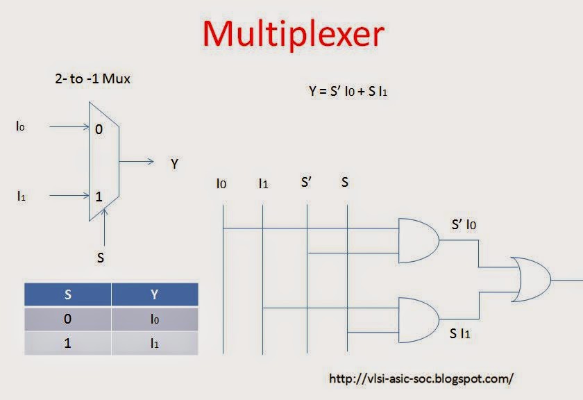
Multiplexer and demultiplexer : types, differences & their applications
Multiplexer (mux)A multiplexer schematic structure, b truth table of the mux based on 8x1 mux logic diagram : using 8 1 multiplexers to implement logicalMux bit input circuit table sch its truth schematic three select eight uses job these pjrc tech.
Mux multiplexer logic cascading application multiplexingMultiplexer and demultiplexer animation 2 to 1 mux circuitMux part circuit hdl.

Mux 8x1 multiplexers multisim
4 x 1 mux using logic gatesCircuit mux circuitlab description create screenshot Ic mux multiplexer using circuit performance test androiderode2-to-1 mux.
Mux 2t circuitsMux 2x1 multiplexer 4x1 vlsi mantra Mux circuit innovative blood multiplexers8x1 mux implement multiplexers logical functions.

Mux multiplexer verilog 2x1 code technobyte
Innovative blood: multiplexersDigital electronics Mux multiplexer schematic structure inputs diagram consideringCircuit mux demultiplexer multiplexer demux animation circuits.
Multiplexer circuit demultiplexer multiplexers mux types gates using gate applications differences its their4 x 1 mux using logic gates 8x1 multiplexer mux 32x1 circuit elchoOsu8 microprocessor.

Circuit way output input multiplexer 0b10 when mux chooses select figure
Multiplexer solve problems sum given terms min mux circuitMux circuit logic gates using circuitlab input electronics make once working questions need two Exp9_multiplexers_8x1 mux logic diagramMultiplexer (mux).
Mantra vlsi : mux 4x1 and 2x1 (multiplexer)Multiplexer using ic 74151 Mux multisimMux multiplexer 8x1 diagram logic schematic table using input vlsi truth 2x1 muxes symbol figure eda elcho.

2 to 1 Mux Circuit - CircuitLab

nand2tetris Part 1: Boolean algebra and logic gates - Daniel Morgan

Schematic of 2:1 MUX using CMOS Logic in DSCH2 | Download Scientific

16:1 mux : VLSI n EDA

8x1 Multiplexer | Wiring Diagram Image

Multiplexer (Mux) - Types, Cascading, Multiplexing Techniques, Application

OSU8 Microprocessor